batch processing
Marker file extraction can most adequately be done in batchmode. However, to tell anslab which type of timing file to create, you must set the
Marker analysis mainly serves the purpose of extracting or generating timing information, that allows to process other data channels in defined subsets. All standard data analysis types check wether timing information is available for the processed file before loading the data and can thus make use of marker-based timing information. The mechanism used for timing in anslab is simple: when a data file is read, anslab looks for an m-file with the same name as the data file, in the folder where the data file is stored. If this m-file exists, it is evaluated as matlab-script. If after evaluation, a valid variable named 'T' exists, timing is based on this variable.
For instance, if for a data file
F:\tex\raw\tex00101.acq
an m-file
F:\tex\raw\tex00101.m
exists and it contains the following text:
T = [...
1 0
1800 1800;...
2 1800
1903.519 103.519];
anslab will recognize 2 valid segment definitions. The first segment
then begins at 0 seconds after file begin and ends at 1800 seconds
after file begin, thus has a length of 1800 seconds. The second
interval
starts at 1800 and ends at 1903.519 seconds after file begin, spanning
103.519 seconds.
The 'marker' analysis type allows you to generate this type of timing
files automatically.
file naming
Timing files are named according to the raw datafile the are extracted from plus a customazible file extension. You can the default extension << .m >> to << .spectral.m >> or << .icg.m >> to create timing files for specific analysis types, but this is not mandatory. Renaming the files manually works just as well.
batch processing
Marker file extraction can most adequately be done in batchmode.
However, to tell anslab which type of timing file to create, you must
set the ![]() marker-options
in the anslab options dialog according to your needs. Basically for
every dialog question given in the non-batch analysis, there is a
default option, that you can use to give your answer for all files in
the batch. Thus, the number of marker channels, their type and name,
the minimum and maximum event duration, events of interest and events
to ignore are all taken from the default settings. Be sure also to
select or deselect the 'ignore subsequent event with identical marker
value if you wish to ignore or not repeated marker values.
marker-options
in the anslab options dialog according to your needs. Basically for
every dialog question given in the non-batch analysis, there is a
default option, that you can use to give your answer for all files in
the batch. Thus, the number of marker channels, their type and name,
the minimum and maximum event duration, events of interest and events
to ignore are all taken from the default settings. Be sure also to
select or deselect the 'ignore subsequent event with identical marker
value if you wish to ignore or not repeated marker values.
IMPORTANT:
Marker
channel analysis ist optimized for one well calibrated digital marker
channel, that has a relatively small set of discrete values (0 to 255
== 1 BYTE == 8 Bit ) . You can use non-integer marker values, several
binary channels with integer and non-integer values, but event
filters will be harder to perform, as comparisons are made at matlab
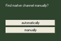
calculation precision. If you are using such a calibrated digital
channel which is labelled 'marker' or 'signal', you can use the
'automatic' channel detection. In all other cases, you must choose the
marker channel manually.
You can set a rounding precision for the marker channel in the marker
options tab, on the \tools\options dialog. This can help filtering
marker values that are not perfectly calibrated to integer values.
You can choose between 4 types of timing
information: binary, digital, analog and fixed.
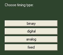
Select 'binary'
to evaluate one or
several data channels, that differentiate only between two values, such
as 'on' and 'off', 0 and 1, or any two numbers. Select 'digital' to evaluate one
channel, that can code a distinct (and small) number of different
values, such as numbers from 0 to 255 (= 1 BYTE / 8 BITS). Select
'analog' to evaluate a
continuously varying data channel (under construction). Select
'fixed' to generate
timing data based only on filelength and filestarttime without a
dedicated marker channel. Each timing type will be described separately
in the following sections.
binary timing
If you have only one dedicated binary marker channel, anslab can load
it automatically and extract timing information without further input.
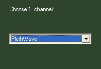
In all other cases, for instance if you wish to use several binary
marker channels as digits of a binary number, select manual channel
selection, enter the number of channels to load, enter the sampling
rate
to operate with, and choose the channels from a list of available
channels.
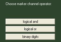
Next, if you chose to load more than one
channel, you can select how to integrate the signal from these channels:
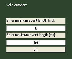
Next you can enter a minimum event duration and a maximum event
duration. Event durations are measured from beginning of a new marker
value to the next value change. Choosing
'0' and 'inf' for minimum and maximum duration will cause
anslab to write one timing line for every marker value change found in
the ( integrated ) marker signal.
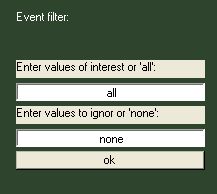
The following dialog give you opportunity to specify special event numbers to extract and special event numbers to ignore. These options allow you to create timing files, that only contain events you are interested in for a specific analysis type. Choosing 'all' and 'none' for events to extract and events to ignore will cause anslab to write one timing line for every marker value change found in the ( integrated ) marker signal.
After this, data is loaded, resampled and analyzed. You can choose to
immediately view the created m-file in the matlab editor.
digital timing
The procedure for digital timing is identical to the one
described for binary timing, except that there are different
integration operations available, if multiple marker channels are
selected (+,-, logical and, logical or).
analog timing
(under construction)
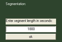
fixed timing
Fixed timing refers to creating timing files based only one file start
time and file length.
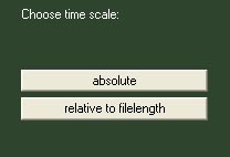
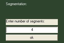
Using this timing type, you can only create a number of intervals of
constant
length, either expressed as a fraction of the file length (relative) ...
or
expressed in seconds (absolute)....